

The hard hat with LED light array above allowed me to test a number of ideas and components. There are 4 ea. Nichia 083 High CRI LED's used in a linear array behind an acrylic optic. The optic is simply a section of 1/2" half round bar stock. The LED's are driven by a prototype, buck "3 speed" converter, in series. Input current to series string measured: low - 27 mA, med - 115 mA and high - 330 mA . The converter is powered by a Makita 1 AMP 18V Li-Ion pak. The measured converter draw: low - 48 mA, med - 108 mA and high - 284 mA.
In addition to a platform for testing out the converter, I wanted to test and evaluate the following ideas:
* Use of an aluminum hard hat as the integral heat sink for a LED source
* Evaluate the thermal status, with a FLIR camera, of the LED source as well as the heat sink form size and shape relative to the LED array and its position.
* The use of a half round optic bar for beam distribution
I left the LED lights on in high for 45 minutes. The hard hat was placed on "lava man" in my back yard at dusk. The plastic and webbing "basket" isolated the aluminum shell from the lava rock and the hard hat was left to dissipation of heat to the surrounding air. There was little breeze to speak of and the air temp was around 27 C . The FLIR shot below was taken at this 45 minute mark:

I took the hat off the lava rock and inverted it and took a FLIR shot of the proto converter:

The converter is a stack of two PCB's and it was tacked to the ceiling of the hard hat with some UV curing epoxy. There was no significant thermal path provided between the converter and the hard hat. This is obviously something that could be brought into play.
Below are some shots of the crude assembly and circuit:

The Nichia 083 LED's were SMD mounted on 3/4" round MCPCB's which I cut down to rectangular shapes of roughly 1/4" x 1/2". I thermally epoxied these next to each other in a milled pocket in a machined bar of 3/4" OD aluminum, as seen above.
The LED bar has 2 ea. #6-32 tapped blind holes which allowed for it to be fastened to the bill of the aluminum hard hat. I put some thermal grease on the mating surface between the bar and bill.

Input leads from the switched Makita "dock" follow up to the converter mounted in the apex of the shell. LED leads in a kevlar sock then come back down and forward where they exit up through the bill and into the LED bar.
Although I would not consider subjecting this hard hat to actual use where impact on the shell would be a possibility, the converter and circuit and dock mounts are well removed from contact with your head by virtue of the inner plastic and webbed "basket":

Certainly a circuit and LED Bar could be integrated into such an aluminum hard hat without encroaching on its primary role of protection. It is apparent that using the hat or visor as an integral heat sink is more than viable and this package here could handle a higher power LED array than the one tested here. In this particular test of concept, the battery pack and its weight and position are certainly ungainly and by far the weakest aspect of the package.
The acrylic lens seats down on the LED's themselves and provides for some condensing of the light output on the horizontal.

From experience with mounting a flood type flashlight on the bill of a base ball cap, I realized that the bill precludes viewing illumination of areas blocked by it. With this in consideration, I angled the LED array down about 15 degrees from the plane of the bill itself which also has a downward slope. This was mostly guess work but ended up being a good guess.
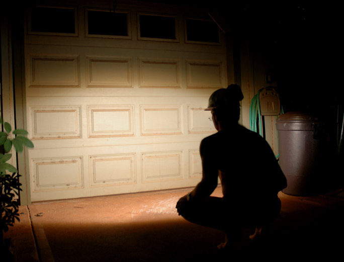
In the self portrait above. I am squatting about 4' from the garage door and looking forward with my head level. The beam distribution favors down and in the foreground and the top of the beam is just about at the blind break of the bill. With the hard hat on, you can see illumination from the beam basically in your complete field of view and yet the beam does not extend much past this.
I have been putting off this "experiment" for quite some time but am glad I finally got around to it. I am quite pleased with confirming some of the ideas I had as essentially effective and viable. The beam pattern is very satisfying and suggestive of other ideas to follow.
To continue in testing thermal conditions as well as the use of a 1/2 round acrylic bar, I strung a series of 6 of the Nichia 083 LED's mounted on MCPCB in a 6" long fixture and drove the string with a Xitanium driver (350 mA)

The 3/4" diameter MCPCB's were set in the bottom of an aluminum "U" channel of 1/16" wall thickness I got from the hardware store. This U channel was then bolted to an angle bar of 1/8" thick aluminum of 2"x 2" dimension. I used #4 screws to clamp MCPCB, U channel and angle stock together with some thermal grease in between mating surfaces.

Above you can see the cross section of the fixture assembly and there is an acrylic 3/4" half round bar set into the U channel and contacting the tops of the LED's.
Below is a beam shot both with and without the acrylic half round bar optic:

Both images were taken with the same manual exposure on the camera so you can see the increase in intensity of the smaller beam resulting from the optic. I ran the fixture for 20 minutes and with the FLIR camera found the aluminum to be within 1 degree C anywhere in the fixture. The ambient temp was 27C and the aluminum of the fixture measured at a max of 43C.